X-Plane is way late when you compare with Flight Simulator for the scenery. It is now time to change that by adding objects to have a simulator less empty, more real.
Object files are text files. Some people create objects directly with a text editor. This is a very long process.
The tools to create X-Plane objects are not many. As far as I know
there is only one. It is Christian Frantz's Object Maker
(
http://www.christian.franz.net/OM/).
The problem is that it is no longer maintained by the author, it creates
only v6 objects and it is Mac only.
As there is no tools to create version 7 objects and as there are conversion tools, we will choose a a tool working with the converters. Blender 3D will be fine bien. It works on all X-Plane platforms (Windows, Mac and soon Linux). And this tool is Freeware.
Last news, I found a tool to create X-Plane v7 objects directly. It is VBuilder3D from Thierry Videlaine. You can it here : http://www.tvi-sarl.com/VBuilder/. But as it is a Windows tool, it is not the universal tool we are looking for.
Since the start of this page, we can use an other tool. It is AC3D.
3 tooles are available for convertion :
The first was Dave Spott's JObjectTool
(
http://x-sky.net/jobjecttool/). This tool was used to create
the scenery New-York.
The second tool is Ben Supnik's ObjConverter
(
http://www.xsquawkbox.net/tools/xptools/). Easier to use, it can also
convert v6 objects to v7.
JObjectTool and ObjConverter need a VRML 2.0 file.
Last converter, the Python script XPlaneExport.py from Jonathan
Harris (
http://www.marginal.org.uk/x-planescenery/). Even easier than
ObjConverter, it can save directly to object v7 format from Blender 3D.
We will see later that there is no perfect and universal converter. So we will use all of them for their own pros and cons.
Long time ago Martin Insulander from Sweden created Wyoming to display v5 X-Plane objects for PC. Next we had X-ObjectViewer ( http://www.xsquawkbox.net/tools/xov/) for Mac and finally ObjView ( http://www.xsquawkbox.net/tools/xptools/) for Mac and PC created by Ben Supnik.
It is very easy to use. Drag the object on the program. If you want to see the object with textures, just drag the texture the file after. It works as well for v6 and v7 objects.
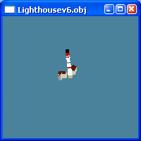
Our example will be to build the main hangar at Beynes LFPF. Why this one ? Well, because it is simple but not to much and also because it is located five kilometers from my home.

First step, we need to analyse the object. Here we have a hangar with 5 parts. There is 3 hangars with a building on each side. On the left it is the club house and on the right a workshop. To keep this simple we will do it with all doors closed.
To find the dimensions is often something difficult.
There is nothing special about Blender installation. You need to download the file from http://www.blender3d.org/ and run the installation.
It is now time to open Blender.
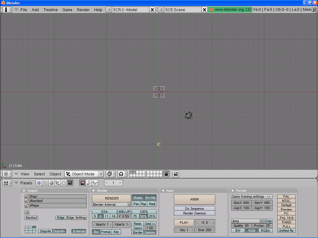
The default screen has three parts. The top menu hide the parameters. Bellow you have two windows each one with its own menu. You can move the separation line and add new windows.
If you pull down the top menu you can see the parameters.

In the File Paths menu we can choose the default path for textures (we will choose our work directory), for Python scripts (choose the directory with the delivered Blender scripts), for the temporary files,...
Looking for the menus you may notice that it does not work as a standard selection window.

To move to directories you must click on the name to open it and on the two
dots to go back. The bar on the left must be moved. The button bellow P
is for choosing an other disk or one of the saved paths.
Once the file is selected, its name comes under the directory name and now
you can click on the button above Cancel.
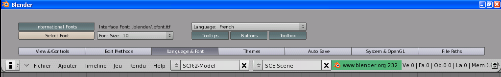
With the menu Language & Fonts you can if you want change the language. Don't forget to check the three buttons under the language button.
There are some other menus but it is enough for now. We can close the parameter part pulling up the menu.
We need to setup our work windows, one to see the object from an other point of view and one to display and run the import/export scripts.


Move the mouse cursor to the separation line and press the Right
Mouse Button. A menu opens, choose Split Area. Then move the
new separation line and click to finish.
Do the same for the other window.
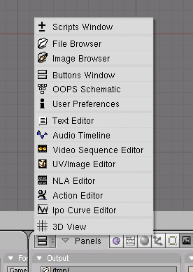
Before ending with parameter, we can choose the Text Editor window to load a script later.

At the end do Ctrl U to save your settings. 
There is more than one way to start. The simple one is to use the start Cube.
We will start from the top. From the View menu, choose the Top view. The start
cube is 2 x 2. The hangar central part is 12 x 25.
First step, we must switch to Edit Mode using the Tab key or the
Mode menu.


 (After).
Select one side with the B key (Block Select).
 Active points are yellow :
  3D view :
With the B key permet de s�lectionner tous les points de la zone, m�me ceux qui sont cach�s (voir la vue 3D). On va beaucoup s'en servir.
With the G key (Grab) now we can change the size of our cube.

To move the points accuratly, we use the grid. If we maintain the Ctrl key,
our points will go to the grid edges. Left Click to set the modification.
Right Click to cancel (useful when you moved the wrong points).
The default value for the grid is 1. As in the X-Plane objects the unit is
meters, our grid will be in meters. Of course it is possible to change this
value for our needs.
It is time to do the most important thing, save our job. We must do it often and keep different files. For this I add the date and sometime the time.

To pull an other side, before selecting the new points with the B key,
we will have to first de-select the previous points. To do this, we
select one point with a right mouse button.
Now we can continue like above. Select one side with the B key,
pull, fix with the left click.
We saw how to move the walls. Now we will see how to create other walls. It is time to use the Extrude function.
We have to create two parts 19x25 meters on each side of the central part. For this, we select all point of the right wall with the B key. Then press the E, confirm and pull the new wall.

|

|
As above, we use the Ctrl key to move the wall on the grid. Do the same on the other side. Now the basement is finished.
We display the front view from the menu View / Front. Our hangar is a little bit low. We are going to change the size as we have already done for our cube.

As usual now, click with the right button close to one point to select, B key to select all points from the roof, G key then pull up with the Ctrl key and finally left click to fix our roof at 6 meters above.

To build the roofs of the three parts, we will use the Extrude function. We select the roof of the left part and we pull the the roof 3 meters high.

The roof is a triangle. To do this, we select the points of the
top to move and press the S key to rapprocher ces points.
This time we must select the front points only. To do this, we
will not use the B key but do a selection point by point maintaining
the shift key.
The 3D view is usefull to do this selection. We change the
the angle of view with the left mouse button and the Alt key.

|

|
We do the same for the back wall. Our hangar start to look as a hangar but we must remove the duplicate points with the button Rem Doubl. A window will show you the number of deleted points.

|

|

|
After doing the other roofs, we must do the side buildings.
As the side does not have 4 points in common, we start from the
basement. We extrude one edge.

As usual, we select the 4 points on the ground and we build the wall with Extrude. Then we select only one side and with G do the roof.

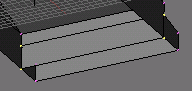
We do the same on the other side and now the 3D model is finished.

It is time to clean up the model. when looking from bellow we see walls to delete. To have a better view we use the Solid mode.

|

|
To delete a face, select the 4 points than press the Del key. In the menu, choose Faces.
|

|
Sometimes when you delete one face there is no effect like in 1/. In fact there is two walls there, the one from the main part and the side part. You need to delete both and select the 4 points of the face to create (see image 2/). To create the face, press the F key.
It is time to apply textures.
For each object, there is only one texture. It must contain all faces of this object. As the space is limited, we need to optimize. For example, set a higher resolution for the part we will come close (from wall of the hangar) and a low resolution for the part you will never be very close (roof, other sides).

Sometimes, we need to modify the image. Between the two versions bollow, we had to remove the fence and change the colors because I took this picture at sunset.

|

|
About colors, now with the digital cameras we have an
interesting thing with the white balance. It is usefull
to have constant colors.
An other photo tip.
We can use two image formats, BMP and PNG.
http://www.marginal.org.uk/x-planescenery/